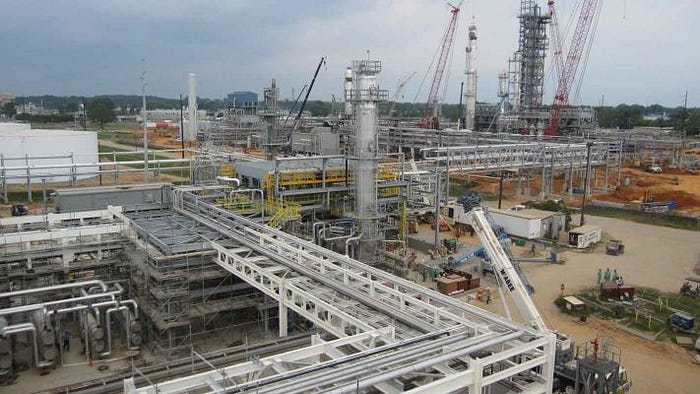
Pipe racks: The main artery of a plant
In process units, pipes often run across several units with lines coming out of facilities. Pipe racks are used to support pipes, cable trays, power cables etc. in petrochemical, chemical and power plants. Many times pipe racks also support mechanical equipment, valve access platforms and vessels. When designing the plot plan for any plant, it is important to design and plan the pipe rack through which piping will run from one unit to the other. In that sense, the pipe rack is the main artery of the unit.

Since pipe racks are typically located in the middle of these plants, they must be constructed first, before they get stymied by tons of equipment. These are some of the important data required before you commence detailed development of a pipe rack:
- Plot Plan
- Client Specification
- P&IDs
- Construction Materials
- Fire proofing requirements
- Statutory requirements
Due consideration needs to be given to the arrangement of pipe rack and structures as extra pipe length builds up the expenses and you can optimize the space and save on structural steel and civil costs. Using innovation in planning and design constructability, enhances the project performance and reduces the overall project cost. Thus, the constructability needs to be finalized at an earlier stage in collaboration with civil discipline and the client.
Inter-connnected pipe racks carry utility and process lines to and from process and utility units and shouldn’t run through process or utility units. And there are unit racks connected to the main rack carrying lines to the respective units via battery limits station. The elevation for these racks must be at a different level than the interconnecting racks.
Whilst, unit pipe racks are the main channels taking the pipes into the units, and therefore they are centrally located and usually elevated. The elevation or height is required to allow vehicle access underneath. Pipe rack width is determined based on the number of lines (also scoping future needs) along with any requirement for cable trays.
Shapes used in pipe rack
The most common shapes used for design of pipe racks are L/T/U/H/Z. The shapes are usually decided based on the space available and optimized use of space and material.
Contingent space
All pipe racks typically include 25% extra contingent space for future requirements. The future space percentage is usually based on client requirements and the type of projects.
Width of Pipe rack
Normally, the width of the rack is 6 m, 8 m or 10 m in single bays or 12 m, 16 m or 20 m for double bays having a maximum of 4 tiers. Usually, the spacing between the portals is taken 6m but it can also be increased up to 8m depending on the size of the pumps that are to be housed underneath.
The stress analysis team provides the pipe rack loads to the civil and structural discipline for pipe rack design. The main types of pipe rack loads are as follows:
- Dead Load (Sustain Load): The weight of piping, valve and load insulation
- Thermal Load: Load by thermal expansion of piping & reaction force due to internal pressure of expansion bellows
- Dynamic Load
- Piping Vibration loads
- Wind load
- Earthquake load
- Live Load: Liquid load for hydro static pressure test
To conclude
Pipe racks have a crucial role to play in the functioning of plans and the support they offer to various equipment, cables and lines. The design of pipe racks is an important aspect of piping design engineering and the designer needs to evaluate the design of the pipe racks and the overall stability of the associated structures. Do you have any tips and suggestions for the optimum design of pipe racks? Please let us know using the responses section below.
