Considerations for pipe rack design for stress engineers
Oil & Gas, Manufacturing Units, Petrochemical & Refineries and other power utility companies rely on pipe stress engineers to perform stress analysis of their piping system. In this article, we’ll discuss design considerations for pipe rack loading and expansion loops.

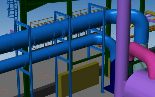
Pipe rack is a vital part of the process of piping. It is a steel frame structure that supports and carries pipes inside the processing plant. It helps transfer the fluid between equipment and storage facilities or utility areas.
Pipe engineers are well versed with expansion loops in the piping system. The expansion loops are added to absorb the thermal displacements inside the piping system. It enables to reduce system stress and limit thermal displacements.
Stress engineers should look into the following while designing a pipe rack.
Pipe Rack Layout Design Considerations
Shapes
There most common shapes of pipe racks are L/T/U/H/Z. Consider choosing the shapes based on the space available.
Future Expansion in Pipe Rack
The pipe rack’s total width should include 25% extra space for future scalability in the unit. The future expansion percentage is usually based on client requirements.
Pipe Rack Width
Usually, the pipe rack’s width is 6 m, 8 m, or 10 m for a single bay or 12 m, 16 m, or 20 m for a double bay having four tiers maximum. The average spacing standard for a pipe rack is 6m. However, it can be exceeded to 8m depending on the size of the pumps housed beneath the pipe rack.
Clearance measures shall be maintained as below:
For Units: Clearance beneath pipe rack shall be 4 m minimum both in longitudinal and transverse directions.
For Offsites: Clearance beneath pipe rack shall be 2.2 m minimum both in longitudinal and transverse directions.
Roads: Clearance shall be 7 m for the main road and 5 m for the secondary road.
The stress analysis engineers provide the pipe rack loads to the civil and structural discipline for pipe rack design.
The common types of pipe rack loads include:
- Dead load
- Thermal load
- Dynamic load
- Piping vibration loads
- Wind load
- Earthquake load
- Live load or Sustained Load
Expansion Loop design and placement
There are no defined measures for designing and placing an expansion loop in a pipe rack in most organizations. So, the expansion loop is designed and located based on user experience. The factors that govern the design of the expansion loop are as below:
- Design operating temperature of the line
- The allowed thermal displacement is 250–300 mm inside a loop and 75–100 mm in outside turns.
- Bigger line sizes require more leg to absorb the expansion.
- The expansion loop is provided at a high temperature. All the loops shall be located around one column only.
- Make lines into a group and install a large size piping to the edge of the pipe rack.
- Install an expansion loop on the condensate line. Place it horizontally to prevent water hammering.
Conclusion
Pipe racks play a critical role in the functioning of plans and their support to various equipment, cables and lines. The design of piping racks is an essential aspect of piping design engineering. If you’re looking for piping stress and flexibility analysis services, consider hiring an engineering company that adheres to industry codes and standards.